
Wow, time flies when you’re a software developer trying to get hired in 2021 and you have to take dozens of virtual interviews before you get completely ghosted by behemoth companies and startups alike! Sadly, between actually doing the interviews and grinding Leetcode problems in preparation for the same, all the madcap mayhem has left me with only a little bit of time to make progress on the project. But progress I have made!
As I said last time, I was all set to do a bunch of tests to ensure that everything worked in the first place. And so far, that’s mostly been what I’ve been doing.
A Difficult Decision
But first, as I mentioned in the kickoff, I had a hard choice to make: what would be the brains behind this thing? The short version is: I could build an analog clock, and stuff a Bluetooth receiver board in there, or I could use an Arduino or Raspberry Pi and do things in code instead of hardware.
And I have made my decision: I’m going with a Raspberry Pi.
Basically, the pros in the Pi’s corner ended up winning by a fair margin. One big initial push for me was that the Nixie driver chips take binary input, so it made sense to go with a solution that provides binary natively. Binary analog clock circuits exist, but they all require a significant time and effort investment to achieve the same result as using this RasPi 3 I had lying around gathering dust. Plus, one feature I was really hoping to build was a built-in display and Plex client so it could be more than just a smart speaker. With the Pi, I can drive the clock, run a Plex client, and drive a small TFT display that hopefully I can turn into something that resembles a CRT. The final nail in the coffin for me was learning that you can turn a Raspberry Pi into a Bluetooth receiver pretty easily. Previously, I had been planning to purchase a separate Bluetooth audio board, but this eliminates the need for that entirely.
So that’s what I ended up doing. Is it a bit lazy and less cool than building an analog binary clock from raw logic gate chips? Yeah. Does it allow me to check of all of my wishlist options, with the only limit being my patience for coding in Python? Very yes. The choice was clear.
With that decided, I could get on with hardware testing.
The Tubes
This being a Nixie project, and me being a huge dork, naturally the first things I wanted to fire up were the Nixie tubes themselves. I had obtained a switching power supply from a certain electronic bay back when I bought the tubes, so the high power requirement was taken care of — the tubes I’m using, IN-12s, have a “strike” voltage of about 160 and an operating voltage of about 140. But as with most neon and neon-adjacent tubes, they have an extremely low operating current, around 2.5mA per digit, so I have to slap a current-limiting resistor on the anode. With all that high voltage in play, I didn’t want to mess around (too much) so I built a quick test rig to hold and supply a single tube.
As you can see, the rig is a bit janky — one of the tube sockets I got has a pin that doesn’t quite make contact with the tube’s pin, so you can see the bit of wire I jammed in there to make it snug. Also, the pins themselves are in a unique arrangement and have solder tabs instead of actual pins. So all in all I’m not thrilled with them. Combine that with how hard it is to get a tube back out of the damn things and I don’t think I’m going to use them in the final build.
But with that said, the tubes work! Somewhat surprisingly, all 6 tubes in the lot illuminate all 10 digits correctly and beautifully. You’ve got to love that orange Soviet neon glow.
The Bit Shift Registers
Next up, I had to test the bit shift registers. These are Texas Instruments SN74HC595s, which each support 8 bits of data with serial input and parallel output. Since each Nixie driver chip takes only a nibble of data (4 bits) in parallel, this means I can drive all six tubes off just three bit shifters — 4 bits per digit grouped into three pairs of digits to represent hours, minutes, and seconds. As a very nice bonus, they’re chainable: there’s a 9th output pin that you can hook up directly into the input of another SN74HC595. Once the chip has received 8 bits of data, any further data will push the end of its register off the stack and on to the next chip.
To test, I did actually end up writing most of the clock code, which will be shared once it’s all cleaned up, but the important thing is that it sends binary serial data out from one of the RasPi’s GPIO pins and that’s good enough for me. I decided to keep it (relatively) simple and send data with the MSB first, and to have the bit shifter for the seconds digits as the first link in the chain. The code starts by sending the hours digits, then minutes, then seconds, which when everything’s all wired up will push the higher-digit bits up the chain to their corresponding shifters.
And as you can see, it works great! The code is sending the right signals, and the bit shifter picks up the bits correctly. We’re seeing the seconds tick up, and split into two nibbles as expected.
The Nixie Drivers
Now all that’s really left is to test the Nixie driver chips. You may have noticed in the image of the tube test that I’m already using one, and that is true. I tested one of the chips immediately after it arrived, and I’ve been using that one to drive my tube testing by manually pulling up the binary input pins. This time, however, I want to ensure that they can take the bit shifter output and convert it into sweet, sweet neon decimal digits.
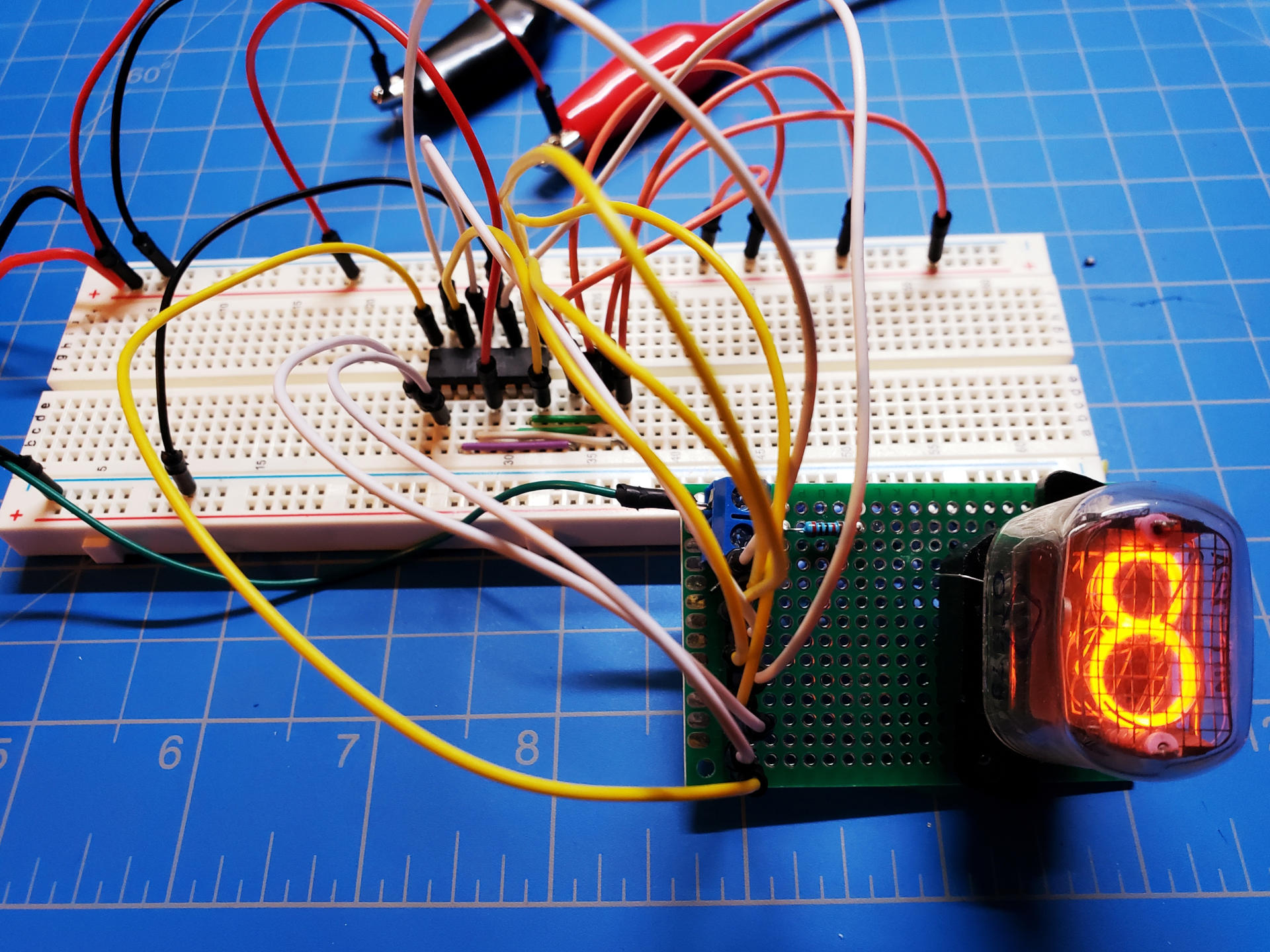
So I wired up an even more janky test rig to run two tubes at once, and…
Hang on, that’s not right…
Turns out it’s really easy to get your wires crossed, especially when all this work is split up into sporadic bursts that happen maybe once a week at most! Luckily the mistakes were all mine — when wiring up the breadboard output from the Nixie driver to the tube, I forgot that the pins count down (meaning they start at 0 then go to 9, 8, 7, etc.) instead of up. For an added bonus blooper, you can see that I’m running the wrong version of the code too, where I neglect to trim the output to 4 bits per digit, so it’s sending a whole 8 bits for the ones and leaving the tens with all zeroes.
Some quick breadboard rewiring later, and…

There it is! Due to the extreme jankiness of this test rig, the tens digit is sitting on the bench, but you can see it tick over in the background when the ones reaches 0 again.
And yes, this lot of tubes has that “charming” quirk where they flipped a 2 upside-down to make the 5. I kind of like it, although I do love the way the unique 5 looks in other tubes. I wonder if there are any IN-12s out there with the non-cheap 5 digits.
So What’s Next?
Next up I’m going to make a wired prototype “module” encompassing all three logic chips needed to drive a unit pair of tubes. This will eliminate some of the extreme danger of running high voltages through flimsy breadboard prototype wires and alligator clips all over the bench, and also cut down on any weak connections due to the same wiring causing weird issues (e.g. occasionally two digits will illuminate unless I hold some of the breadboard wiring in just the right position). Along with that I’d like to make a two-tube testing rig, since this current setup just increases the risk of death even more.
Once that’s done, and once I’ve cleaned up the clock code a bit more, the clock portion of the Nixie clock will be nearly complete. I’m still trying to decide whether to pick up some dots for colon separators between the units, but that’s a minor issue. I might have to start getting into PCB design soon, and even start sketching out ideas for the enclosure.
Oh, and I guess I can try playing some music through this thing.
In any case, stay tuned for the next update, which should happen much sooner!